Well, last night I upgraded from the eZMSP430 to a proper JTAG and header board.
Earlier this week, I order a few bits and bobs to aid development of front panels for Expat Audio products.
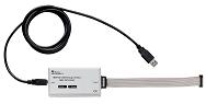
Firstly, I ordered an MSP430 USB FET tool. This is simply a USB to Jtag adaptor. It allows me to connect to any MSP430 board that has a jtag header. It allows connection through both regular 4-pin jtag and "spy-bi-wire" - TI's proprietary two wire jtag-connection.
Installation was a breeze, seeing as I'd already installed the exMSP430, all the drivers were already in the system.
For my target system, I didn't see the point in developing new boards at the pcb-fab, so instead, I went to http://www.sparkfun.com and ordered one of their MSP430 target boards... which is essentially an MSP430
 processor, the basic passives and oscillator, all on one board, with regular through hole pin headers.
Doing this would be even simpler than using a through hole DIP MSP430, as the header board actually has the passives and the JTAG header ready to go. The link for the header I used was: http://www.sparkfun.com/commerce/product_info.php?products_id=596
These steps may have seemed simple to a professional, but quite honestly, I was terrified of it "just not working". There's nothing worse than something just not working... I'm a terrible fault finder :(
So, I fired up the IAR tools, and opened the default project they have for the eZMSP430-F2013 board. I figured that I needed to change the options to show the new chip being used (the MSP430F2131 instead of the MSP430F2013, and also change the jtag interface from the ez430 to the standalone USB interface.)
Turned out easier than expected, I simply went to the PROJECT -> OPTIONS page and went from there. I selected the MSP430F2131 as my processor, and then selected TI USB FET as the JTAG.
From there, I hit compile - nothing bad happened, and then I hit "debug" and watched it download the code to the target board. It all worked, I was toggling pin P1.0 high and low, and watching the voltage change on my multimeter.
The next step is to build a protoboard with my chosen switches, and program multiple switches and LED's all together.
Until next time :)
/R


No comments:
Post a Comment