A new controller board, this time, something that responds to a single button press to change configurations, and sends out a serial SPI stream that will tell a device how to reconfigure itself.
Simple stuff really. or should i say.. "Apparently"
Keith thought the board should be named after a welsh city -- "Prestatyn" ... because it sounded like "press that in".
I'll add a picture of the board that was developed later on this evening. My MSP430 code was a little poor, leaving me with stack overflows and a board that would stop working with the debugger. What a pain :(
one of the registers USIIFG was permanently set, and needed resetting. A small code change set this appropriately, and somehow, the board now works :)
more details to come.
/R
Wednesday, December 10, 2008
Sunday, August 17, 2008
Mic Front end and Controller Prototype complete!
I'm a seriously happy bunny. This weekend, I spent some time expanding the switching ability of the processor from one to three switches.
This was done by expanding the interrupt service routine that runs for the single switch (on GPIO port P1.x) to look at another input on the GPIO port.
However, there weren't enough pins on P1.x - because some of those pins are used for the JTAG interface. So, I had to use some of the pins from P2.x - which cause me to have another Interrupt Service Routine being kicked off when I pressed the button on P2.x
A minor pain in the Ass, the major thing I learnt was how to convert the bits in the registers that control the GPIO ports into hexidecimal numbers. That is... if there are 8 pins on the port, and I only want to control the bottom four, then the binary setup would be: 0000 1111
In Hex, that would make 0x0F
So, the tough one for me was 0000 1100 - which I got confused on and wrote 0x09. I was hungover. that's my excuse and I'm sticking to it. Anyway, turns out, it should have been 0x0c.
Thats where another precious hour was lost. :(
Anyway, here's a basic video of things working. Next step - convert to PCB.
:)
Tuesday, August 12, 2008
Toggle and Debounce!
A little bit of basic breadboarding, a little bit of code modified from the web and TI's free source code.
The buttons used are made by highly electric. (I think they are the PB613). They are simple push to make switches. There is no locking system, they don't toggle. Push push to make contact. They integrate a cool LED though. I got them from Rapid Electronics. http://www.highly.com/product/ca2/3-7.pdf,
The software code was originally written for the eZ430-F2013, which is a Spy-Bi_wire board. The output LED was set up to be on P1.0 and the input was P1.4. However, the header board from Sparkfun is set up for 4 wire JTAG. I'm not quite sure how to switch it to Spy-Bi-Wire.
Anyway, P1.4 on the F2131 shares a pin with one of the JTAG pins. So, when I did some basic debugging, as soon as I hit the switch, the JTAG Emulator would lose it's link. So, a little change in the code changed the input pin to one of the unused pins, and voila, the video below was made. :)
The code itself is simple. The ports are set up then the device goes into low power mode. Any change on an input pin wakes the device up from low power mode and then waits 20mS and checks if P1.3 is low. If it's still low, then obviously, the button is pressed. :) at which point.. TogGLE! :)
Check out my assistant below - and the short demo of my code working.
Cheers
Rochey
Upgrading to real MSP430 tools.
Well, last night I upgraded from the eZMSP430 to a proper JTAG and header board.
Earlier this week, I order a few bits and bobs to aid development of front panels for Expat Audio products.
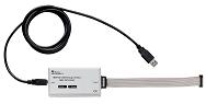
Firstly, I ordered an MSP430 USB FET tool. This is simply a USB to Jtag adaptor. It allows me to connect to any MSP430 board that has a jtag header. It allows connection through both regular 4-pin jtag and "spy-bi-wire" - TI's proprietary two wire jtag-connection.
Installation was a breeze, seeing as I'd already installed the exMSP430, all the drivers were already in the system.
For my target system, I didn't see the point in developing new boards at the pcb-fab, so instead, I went to http://www.sparkfun.com and ordered one of their MSP430 target boards... which is essentially an MSP430
 processor, the basic passives and oscillator, all on one board, with regular through hole pin headers.
Doing this would be even simpler than using a through hole DIP MSP430, as the header board actually has the passives and the JTAG header ready to go. The link for the header I used was: http://www.sparkfun.com/commerce/product_info.php?products_id=596
These steps may have seemed simple to a professional, but quite honestly, I was terrified of it "just not working". There's nothing worse than something just not working... I'm a terrible fault finder :(
So, I fired up the IAR tools, and opened the default project they have for the eZMSP430-F2013 board. I figured that I needed to change the options to show the new chip being used (the MSP430F2131 instead of the MSP430F2013, and also change the jtag interface from the ez430 to the standalone USB interface.)
Turned out easier than expected, I simply went to the PROJECT -> OPTIONS page and went from there. I selected the MSP430F2131 as my processor, and then selected TI USB FET as the JTAG.
From there, I hit compile - nothing bad happened, and then I hit "debug" and watched it download the code to the target board. It all worked, I was toggling pin P1.0 high and low, and watching the voltage change on my multimeter.
The next step is to build a protoboard with my chosen switches, and program multiple switches and LED's all together.
Until next time :)
/R
Monday, August 11, 2008
a grand update
It's been quite a while since I last posted/blogged.
So - tendollaaudio has now been morphed into Expat Audio. A collaboration with another groupdiy member SSLTech.
Expat Audio's website can be found at www.expataudio.com. It still needs a little work though :)
We currently have one main product that we sell. An addon board for the popular Gyraf GSSL DIY compressor that makes it work like the original compressor it was designed to mimic.
However, we have other things up our sleeve :)
I am currently rolling up my sleeves to develop control software on an MSP430F2013. Every product with any kind of digital control needs buttons, knobs etc. The MSP430 has shown to be an ideal platform to develop on.
Whilst it's nothing big to speak about, so far I've managed to write some code that detects a button press, waits for debounce to finish, then tests the pin again to see if it's still pressed. Based on that button press, the software then toggles an LED.
The next challenges are:
Develop the same thing accross multiple pins.
Develop a board that will spit out SPI data to a string of LED's and beyond.
thats all for now.
Tuesday, November 21, 2006
Power Supplies Rethink
Designmaster from Groupdiy sent me an interesting PM regarding my Power Distribution plans.
"How do you want to make the 5V for the ADC. For example the PCM4202 needs 65mA for the 5V analog voltage. You have 18V going to the board.
This will result in over 0.8W of dissipation loss and will generate heat which is not the best for thermal noise performance. I would recommend an additional supply rail with lets say more than 5V for the ADC or DAC may be 7V than you have the option to use a 5V voltage regulator on the board and than you will get a nice and low-noise supply.
How about 48V for phantom powering if you plan to go for a MIC Input board with integrated ADC? "
That made me think a little further. My initial plan was to only have a single "Hard Drive" type power connector. However, I soon needed more connectors (5.. not 4... )
So, a little more thought, means that I could have a 4 way digital connector and a separate analog connector. It would also means that my supply boards can be completely separate on the board.
Nice :)
Tuesday, November 14, 2006
Getting back to basics
I've been so distracted by new projects recently, that I forget why I did all this:
I wanted an AD-DA with ADAT connectivity. Simple. Easy.
A recent post on Groupdiy by Svart reminded me of this. I've spent so much time trying to get the interconnect sorted, that I lost sight of what I wanted.
So -- with the interconnect almost sorted - it'll soon be time to get back to what I really wanted to do :)
3 actions:
1 - complete standardised interfconnect
2 - Get PCM4204 and PCM4104 EVM's and ADAT Cards made - test.
3 - If successful, optimise EVM's for easy DIY production. :)
Tuesday, October 24, 2006
Motherboard connectors (attempt 1)
To make the system work with ribbon connectors etc, here's a suggested pin requirement. Please comment...
it makes 19x2 in total... 19x 0.1" = 1.9" long, 0.2" wide connector.
POWER
+18VDC - Analog
AGND
-18VDC - Analog
AGND -
Analog12VDC - Digital Supply
DGND
Requirement: 3x2 0.1" connector
Clocks
FS - Typically 44.1kHz
DGND
256fS - 256xSampling Frequency
DGND
512fS - 512xSampling Frequency
DGND
Requirement: 3x2 0.1" Connector
Control
SPI - CS (SPI Chip Select)
DGND
SPI - SCLK (SPI Serial Clock)
DGND
SPI - DIN (SPI Data In)
SPI - DOUT (SPI Data Out)
SCK - I2C (I2C Clock)
DGND
SDA - I2C (I2C Data)
DGND
Requirement: 5x2 0.1" Connector
Audio (Left Justified)
LRCK (Typically the word clock brought in from the clock source)
DGND
BCK (128fS or 256fs)
DGND
Data (Left Justified Data)
DGND
AES+ (S/PDIF or AES Data)
DGND
AES- (S/DPIF or AES Data)
DGND
EXTRA1
DGND
EXTRA2
DGND
EXTRA3
DGND
Requirement: 8x2 0.1" Connector
API 500 series
I recently did some work in Eagle (Cad software for PCB's) to create a library for the API500 (http://www.apiaudio.com/5006b.html) standard.
http://www.prodigy-pro.com/forum/viewtopic.php?t=18715
This standard looks to be an awsome standard for DIY'ers to standardise around, although I do have some concern for it's ability to deal with digital audio.
For instance, the only supplies in the standard are ±16VDC supplies. This is obviously aimed at the analog signal chain supplies. Not knowing enough about noise in digital and analog systems makes me concerned that a digital product could really spoil the supply, not only in the card that contains the analog and digital, but also the rest of the box (the other 5 units in the lunchbox).
Such "analysis" of the card and it's format really made be re-evaluate the motherboard plan that I was doing, but also look for an alternative sub-rack system. A post on group-diy pointed to something called a Frac Rak - made by Paia Electronics. http://www.paia.com/fracrak.htm
Someone mentioned in the thread that the Paia board wasn't strong enough in comparison to the API lunchbox. However, a little more research into the Fracrak shows that it is incredibly popular in the DIY Synth market. Those folks are pretty much doing what we're doing here, except that their boxes are more fixed in place (at the geeks home) :-)
I kept on chewing onthis thought, wondering on how I could strengthen the box, how I could make it so that card edge connectors could remain in place, even when the unit is under stress.
The conclusion I came to was that if you were really serious about making the unit mobile, you'd flight case it on its own (in an SKB like case). AS for card edge connectors... forget it. I'm still tempted to use ribbon connectors with 0.1" spacings. That way, if these is some bending, the card mounted vertically (e.g. the mic amp) isn't going to put pressure on horizontal board (the motherboard).
In the case of the system that will mainly be individual cards that can have audio chained from one to the other, then there isn't so much of a need for a control processor or CPLD. The main use for a motherboard system of such a kind is in the distribution of shared resources - power, clocks, control (SPI and I2C) etc.
My design experience in these fields is limited, however, I have seen many implementations in Pro Systems, and asked many a question. Any comments you have are appreciated.
Cheers,
R
Subscribe to:
Posts (Atom)

